
Rotary Valve: Rotor Contact Detection Systems
Q & A: What to look for when purchasing or retrofitting your next rotary valve
Rotary valve rotor contact detection systems have been getting more popular in recent years. Many of the leading sanitary rotary valve manufactures now offer a system that monitors electrical isolation of the valve’s rotor to the housing, alarming when rotor to housing contact occurs. More and more food, dairy, nutraceutical, and other sensitive product manufactures are looking at these rotor contact detection systems as a way to protect their product from metal contamination, and to prevent damage to expensive equipment.
With all of the options available on the market, one can quickly become confused by all of the acronyms, control options, and misinformation surrounding these systems. The goal of this article is to provide answers to the basic questions of how these systems work, and what you should be looking for when selecting your next rotary valve rotor contact detection system.
PPS has been providing cutting edge Rotor Contact Detection Systems since the technology’s beginning. View more on Powder-Solutions’ Rotor Contact Detection Systems here.
Q: How does rotor contact detection work?
A: Rotor contact detection begins by electrically isolating the rotor from the housing and endplate assembly. Usually this is accomplished with ceramic ball bearings or a ceramic coating on the rotor shaft. Once the rotor is isolated from the housing, the electrical resistance between the two can be monitored. When contact occurs, there is a short in the circuit and the controls alarm to indicate the contact. In essence, the control modules provided by the manufactures are glorified ohm meters with some alarm outputs and other adjustable settings. To make the rotor detection system failsafe, there is usually a resistor wired in parallel to the housing and rotor. The controller sees this resistance as a normal circuit. When there is a lead break or open circuit in the system, the controller sees infinite resistance and alarms of a circuit fault. This prevents the system from running if a wire is damaged or if someone leaves a connector unplugged.
Q: How do you make electrical contact to a spinning rotor?
A: This is one of the biggest challenges of producing a proper functioning system and where manufactures spend the most resources in development and manufacturing. There are a couple different ways this is accomplished in systems on the market today. One is with a slip ring assembly. Slip ring technology is a well-proven, reliable means of maintaining solid electrical contact with little to no “noise” (low resistance variance). Devices like this tend to be very expensive, and is one of the reasons for the high cost of some of these systems. The other device used to contact the spinning rotor is a carbon copper brush, similar to what you find on brushed motors like the drill or sawzall in your workshop. These style brushes are good for conducting currents but can be sensitive to heat and contamination, causing resistance through the contacts, which can interfere with operation of these very sensitive systems.
Q: What do you get with the rotor contact detection system for controls?
A: With limited exceptions, what you will get from the manufacture is a module that you will mount inside an appropriate panel and possibly some connecting cables. The module will need to be wired to the rotary valve and to the plant’s PLC. It will output alarms to the PLC in the event of rotor contact or a circuit fault. Some of these modules come with or have optional software that can be used to adjust settings and track alarm history.
Q: How are the controls integrated into my rotary valve and system?
A: Most rotary valve rotor contact detection systems use simple open/close switches on the control module for the contact and circuit fault alarms. Some have separate switches for these while others tie both alarms into one output. It is helpful to have separate alarms for troubleshooting to indicate what the alarm is for. Some of the controllers also have a “contamination alarm” for when the controller sees low, but not too low to be contact, resistance measurements. You can use the inputs to simply notify operators of an issue, or to shut down the rotary valve or even the entire system in the event of a contact. It all depends on your system and how you want to operate it. In any case, the valve should not be allowed to start up when an alarm is present for obvious reason.
Q: What are the limitations of these rotor contact detection systems?
A: First, don’t be fooled into thinking that these systems will solve all of your rotary valve damage problems. They will only tell you when there is metal contact and prevent further damage if you use the alarm to shut down the valve. They can’t prevent what caused the metal contact in the first place. If you currently have problems with valves becoming damaged by improper handling and assembly, adding one of these rotor detection systems will likely increase downtime and maintenance work unless you assure operators and maintenance staff is well trained on both basic rotary valve operation as well as operation of the rotor contact detection system. If you are looking at retrofitting one of these systems to an existing rotary valve, it is critical that the valve be 100% free of damage. It will likely be necessary to rebuild a used valve before adding the contact detection system.
Second, let’s make sure everyone understands that these rotor detection systems do not turn your rotary valve into a metal detector. If metal from upstream passes through the rotary valve without bridging the rotor and housing, no alarm will occur. A metal detector downstream of the rotary valve is still needed to assure no metal contamination of your product.
Another limitation of some rotor detection systems is running materials that have some level of conductivity. Things like CIP fluids, wet products, or even powder with high moisture content can cause issues. Some of the systems available have settings to deal with these types of materials while others do not. If you will be running anything conductive through your valve, make sure the system you select can handle it.
Q: What are some of the common problems with these systems?
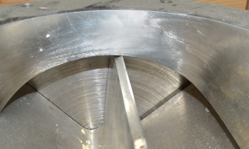
A: Troubleshooting metal contact alarms can be one of the most frustrating endeavors that any maintenance technician has dealt with. Sometimes the area of contact inside the rotary valve can be so small that you can barely see the spots on the housing and rotor that are contacting. Fixing these types of contact can take multiple attempts of repair, re-assembly, and testing to resolve. In the event of a larger contact, parts may need to be completely resurfaced to remove the damage. This can all lead to extended downtimes. But remember this is all in an effort to avoid catastrophic failure of the valve and contamination of the product and system downstream.
While these systems are all self-monitoring, when an electrical problem does arise it may require a skilled electrical technician who is familiar with the rotor contact detection system to diagnose. Manufacturers in general have been slow to provide helpful troubleshooting solutions with their rotary valve rotor detection systems. With some of the software programs available you can use a laptop or system HMI to view screens that will assist in troubleshooting by showing real time resistance values as well as controls to turn alarm outputs off during maintenance to prevent system interference. From our experience, local resistance readout at the valve is the best troubleshooting aid. But this requires technicians to carry a laptop and for the control module to be mounted in close proximity to the valve. Having the control module in a panel farther away, or central HMI display of software only, limits the capability of the software to help in troubleshooting contact issues.
If you need help in your selection of a rotary valve including rotor contact detection, Powder Process-Solutions is your best resource. PPS has been on the leading edge of rotor detection systems since first introduced in 2006. We have installation and field service experience with many of the systems on the market and know the benefits and limitations of each. We also offer training on most of the makes and models of valves available as well as helpful solutions that will provide superior system operation and troubleshooting technology.
Do you have any additional questions regarding rotor contact detection systems or rotary valves? Submit your question here or call Powder Process-Solutions at 877-933-2556.
